Load Cell System Basics
Utilizing the Data from Your Load Cell
The output of a Wheatstone bridge is an analog signal, usually expressed in millivolts per volt of excitation. The signal from a strain gage has to be “conditioned” before it can be digitized by an ADC (analog to digital converter). A signal conditioner can be a separate device or, in the case of a digital display, an internal component. A signal conditioner is a device that converts an electrical signal into another form of signal that is more useful to the user. Load cell signal conditioning may include amplification, attenuation, excitation, filtering and isolation. For more information on signal conditioners, click here.
- Amplification refers to the conversion of a small signal into a proportionally larger signal, ex. mV to V.
- Attenuation is the opposite of amplification.
- Excitation is the external application of electrical voltage applied to a transducer for normal operation.
- Filtering removes unwanted noise within a certain frequency range.
- Isolation is used to break ground loops, blocks high-voltage surges and reject high common-mode voltage, protecting both the operators and the measuring equipment.
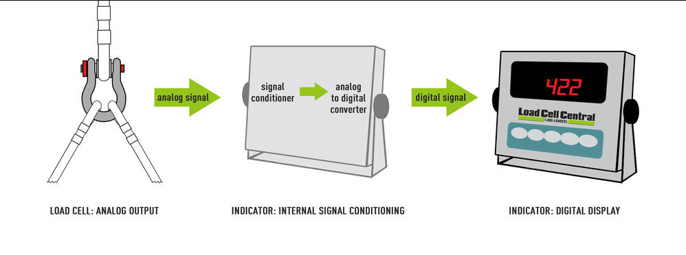
The complexity of your weighing application dictates which devices you require to interpret your load cell signal. In the example below, the display is connected to the load cell and the signal conditioning is all done as an internal function of the display. The signal is then converted from analog to digital, and can be seen as a numeric weight.

In a more complex system, such as a batch weighing system the signal conditioner can be a separate device to prepare the signal for further processing. In batch weighing systems, it can be sent to a computer or PLC (programmable logic controller). The PLC uses the output of the signal conditioner to move a conveyor, start filling a tank, stop filling a tank or switch ingredients in a batch.
Applications may require data to be recorded at specific intervals or in a continuous stream. Below is an example of a load cell system being used to monitor the traffic load on a bridge. In this application, multiple load cells would connect to a signal conditioner via a junction box and then to a computer. Data logging software allows the user to view recorded data aids in data analysis. Information such as load interval, duration, and maximum load are automatically calculated and recorded. Once a load cell system communicates with a computer or PLC, the possibilities are truly endless.

The Importance of a Junction Box
In a multi-cell weighing system, each load cell will exhibit a slightly different mV/V output. Load cells with a nominal output of 3mV/V from the factory will have an actual output varying from 2.9 to 3.1mV/V. Junction boxes perform a trimming function to make up for these slight differences.
In this example, there are four internal load cells in a floor scale. When the system is calibrated, each signal is “trimmed” within the junction box to return virtually the same mV/V output when a known test weight is introduced. This process ensures that the same load will read the same regardless of load placement or orientation. This is particularly imperative in applications weighing products that aren’t self-leveling, such as dirt, flour, concrete, etc.
Junction boxes also perform a summing function that combines the outputs of the individual load cells in such a way as to appear to the digital indicator to be one load cell bearing the load. The combined signal is proportional to the combined mV/V output of the cells. For example, 4 load cells with a 3.000 mV/V output each will be “summed” via the junction box so that the output to the indicator will be 3.000 mV/V.
Calibration of a Weighing System
Before any weighing system can be used it must be calibrated. The purpose is to convert the output voltage to a user-defined value. In other words, the data processing components of the system have to be told how many mV/V are equal to a pound. During calibration, a known weight is applied to the load cell by a calibration press. The calibration technician programs the indicator to know that the mV/V output generated is equal to the known weight. For example, if a 500 lb load is applied to a system and the output is 1.025 mV/V, the indicator is programmed to identify a 1.025 mV/V signal as 500 lb.

This process is repeated at specified intervals between no load and full scale in order to determine linearity which ensures accuracy. A properly functioning load cell will produce a linear (proportional) output enabling the indicator to directly convert the signal from mV/V to pounds or kilograms.
